ELECTRICAL SAFETY TESTING REFERENCE GUIDE
Hipot, Insulation Resistance, Gound Bond, Leakage Current, Impulse Winding
Reference Guide Contents
OverviewProduct Safety Tests
- Dielectric Strength - Hipot Test
- Ground Continuity, Polarization, and Ground Bond Tests
- Insulation Resistance Test
- Leakage Current Test
Choosing the Right Test Equipment
Applications
Standards
Glossary of Terms
Need Assistance?
Hipot Test Equipment
- AC Hipot Testers
- AC/DC/IR Hipot Testers
- Multi-Channel Hipot Testers
- AC/DC/IR/GB/LC/Dynamic Function Electrical Safety Analyzer
- AC/DC/IR Hipot with Corona Discharge Detection
- Ultra-High Withstand Voltage Hipot Analyzer
Leakage Current Test Equipment
- AC/DC/IR/GB/LC/Dynamic Function Electrical Safety Analyzer
- Capacitor Leakage Current/IR Meter
- LC/IR/PD Battery Cell Insulation Tester
Ground Bond Test Equipment
LCR Meters
Wound Component Testers
- AC/DC/IR/DCR Hybrid Wound Component EST Scanner
- AC/DC/IR/Impulse(Surge)/DCR Wound Component EST Analyzer
- Impulse Winding Tester
Battery Safety Testers
Chroma Systems Solutions
19772 Pauling
Foothill Ranch, CA 92610
949-600-6400
Request a quote
 Get our Newsletter: Click the link below to register.
Follow Us
![]()
![]()
![]()
![]()
Test Applications
Appliance Testing
In testing a typical 120/240V AC appliance, the test voltage should be applied between line and neutral (tied together) and the chassis ground (exposed metal parts). A corded product adapter fixture containing a receptacle with line and neutral terminals connected together is a convenient accessory for such tests. The fixture also provides a convenient ground connection for ground continuity tests.
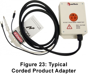
If the appliance is double insulated, wrap the product in foil and use the foil as the ground reference. To test hard-wired appliances such as electric ranges with both 120 and 240 circuits, it is necessary to break any ground return connections between the two voltages before starting the test.
Since the object of the test is to test the insulation only, the test voltage should always be applied between ground and all operating circuits tied together (with all power switches closed; i.e, with the power switch ON) and never between line and neutral circuits.
Motor Testing
Since motors operate at elevated temperatures, the industry has adopted a standard of 40°C as the reference temperature for insulation resistance measurements. Therefore, if you run tests at any other temperature, you must apply a correction factor to the results. A typical chart for determining the correction factor is shown in Figure 24. To find the correction factor, draw a vertical line from the actual winding temperature up to the characteristic curve.
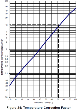
At the point where it crosses, read the value of the correction factor. Multiply the measured value by this factor to obtain the correct value at 40°C.
A "polarization index" is sometimes used to evaluate large motors being tested for the first time. This index, which takes into account several time dependent characteristics such as dielectric absorption, is calculated by dividing a 10-minute IR measurement by a similar 1- minute IR reading.
Insulation resistance measurements are also very valuable for checking motors that have been installed and operating for some time. By taking periodic measurements of insulation resistance over a long period of time, any degradation in insulation can be detected before real damage occurs.
Such tests are also valuable for motors subjected to flooding or very high humidity. After the winding has been baked dry, an IR test can verify its readiness to be placed back into service.
Transformer Testing
There are a number of tests that can be performed on transformers and coils such as inductance, mutual inductance, DC resistance, turns ratio and electrical safety tests including dielectric strength and leakage current. This article will deal primarily with electrical safety and the standards covering transformer testing.
In designing a product, it is important to select a transformer that has been tested in accordance with an appropriate standard for the intended use of that transformer. From a manufacturer's standpoint, the appropriate standard depends upon the industry to which the transformer will be marketed and the intended use of the transformer.
As an example, a transformer designed for the medical industry has lower leakage current and higher dielectric strength requirements than a general-purpose power transformer. Similarly, the requirements for an isolation transformer are completely different from those of a power transformer.
There are a wide variety of standards that cover transformer testing. Some of the more common standards for transformer design and testing are listed below. Components such as transformers that meet the requirements set forth in standards are generally referred to as "recognized" components in the USA and "certified" components in Canada.
A Recognized/Certified Component Directory (RCD) is available which contains such components. Regardless of the standard, the requirements for electrical safety testing are similar and include hipot and leakage current tests.
UL506 Specialty Transformers
This standard covers the vast majority of power transformers that are rated at less than 10kVA.
UL1411 Transformers and Motor Transformers for use in Audio-, Radio- and Television-Type Appliances
Most specifications are similar to UL506 with additional requirements for specific flame retardant material used in the manufacture of the transformer.
UL1876 Transformers for use in Electronic
Equipment, Isolating Signal and Feedback
CSA C22.2, No. 66-1988 Specialty
Transformers
This standard is similar to UL506 with some differences.
CSA C22.2, No. 223 Power Supplies with Extra-Low-Voltage Class 2 Outputs
The hipot test or dielectric withstand test is designed to check that the transformer can withstand a high potential between primary and secondary windings, primary and ground, and secondary and ground (see Figure 25). It should be noted that the windings should never be left open during hipot testing and the core should normally be connected to the low side of the tester.
If the ratings between winding and core are different from one winding to another, connect the high side of the tester to the winding with the higher rating and the other to the low side.
The hipot voltage that the transformer can withstand is based upon the creepage distance between the two measurement points and the insulating material being used.
The hipot test voltages are outlined in the individual standards. Typical requirements for dielectric withstand on power transformers rated for 250V or less can be as low as 1500V for UL544 and as high as 4000V for EN60601. Transformers designed for medical applications are generally tested at higher voltages. It is also important to note that the hipot test is often performed after the transformer has been subjected to an abnormal or fault condition.
The leakage current is also checked between the primary and secondary/core. This test is designed to determine how much current could flow from the ground side of the secondary and core back through a human body. The amount of leakage current that can flow is based primarily upon the amount of capacitance between primary and secondary, and primary and core. In this test, the transformer is connected to the line voltage that is rated at 120VAC. The leakage current is then measured from the secondary and core back to ground. The lower the leakage current, the better the transformer. Limits for leakage current vary depending upon the standard. However, <100mA is typical and <10mA is achievable.
In summary, testing of transformers, especially those with multiple windings, can be complex. In selecting the test voltage to be applied, the appropriate standard, how the transformer will be used, and the voltage rating must be considered. Each relationship, primary-to-secondary, primary-to-core and secondary-to-core, etc., must be checked.
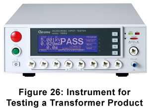
A leakage current test determines how much current could be available to an operator under a fault condition such as loss of ground. Because of the number of test connections required, a hipot tester with a matrix scanner can be useful in automating the testing procedure. The use of a matrix scanner allows the windings to be connected together and the voltage to be applied between various points on the transformer without the intervention of an operator. Figure 26 shows a typical hipot tester with a matrix scanner. Additional measurements such as a DC resistance check of the windings can also be incorporated when a milliohmmeter is also connected into the system.
Electrical Component Testing
In testing electrical components, clearly identify the points between which the insulation should be tested. Apply the test voltage only between those points and not between points that should be not stressed. Connect all those points together before making the test. You should also consider the effects of transients, step changes, and charging currents when designing tests of electrical components. In many cases, ramping is required to minimize such effects.
Keep reading: Nationally Recognized Testing Laboratories (NRTL’s)