ELECTRICAL SAFETY TESTING REFERENCE GUIDE
Hipot, Insulation Resistance, Gound Bond, Leakage Current, Impulse Winding
Reference Guide Contents
OverviewProduct Safety Tests
- Dielectric Strength - Hipot Test
- Ground Continuity, Polarization, and Ground Bond Tests
- Insulation Resistance Test
- Leakage Current Test
Choosing the Right Test Equipment
Applications
Standards
Glossary of Terms
Need Assistance?
Hipot Test Equipment
- AC Hipot Testers
- AC/DC/IR Hipot Testers
- Multi-Channel Hipot Testers
- AC/DC/IR/GB/LC/Dynamic Function Electrical Safety Analyzer
- AC/DC/IR Hipot with Corona Discharge Detection
- Ultra-High Withstand Voltage Hipot Analyzer
Leakage Current Test Equipment
- AC/DC/IR/GB/LC/Dynamic Function Electrical Safety Analyzer
- Capacitor Leakage Current/IR Meter
- LC/IR/PD Battery Cell Insulation Tester
Ground Bond Test Equipment
LCR Meters
Wound Component Testers
- AC/DC/IR/DCR Hybrid Wound Component EST Scanner
- AC/DC/IR/Impulse(Surge)/DCR Wound Component EST Analyzer
- Impulse Winding Tester
Battery Safety Testers
Chroma Systems Solutions
19772 Pauling
Foothill Ranch, CA 92610
949-600-6400
Request a quote
 Get our Newsletter: Click the link below to register.
Follow Us
![]()
![]()
![]()
![]()
Insulation Resistance Tests
As the name implies, an insulation resistance test measures the total resistance between any two points separated by electrical insulation. The test, therefore, determines how effective the dielectric (insulation) is in resisting the flow of electrical current. Such tests are useful for checking the quality of insulation, not only when a product is first manufactured but also over time as the product is used. Performing such tests at regular time intervals can detect impending insulation failures before they occur and prevent user accidents or costly product repairs.
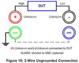
As shown in Figure 15, the 2-wire ungrounded connection is the recommended setup for testing ungrounded components. This is the most common configuration for testing 2-terminal devices such as capacitors, resistors, and other discrete components.
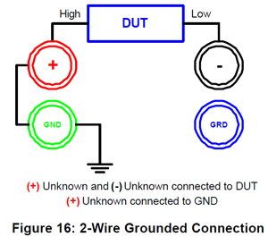
Referring to Figure 16, the 2-wire grounded measurement is the recommended connection for testing grounded components. A grounded component is one in which one of its connections goes to an earth ground, whereas an ungrounded component is one in which neither connection goes to earth ground. Measurement of insulation resistance of a cable in a water bath is a typical application of a 2-wire grounded connection.
Measurement Procedure
An insulation resistance test usually has four phases: charge, dwell, measure, and discharge. During the charge phase, the voltage is ramped from zero to the selected voltage, which provides stabilization time and limits the inrush current to the DUT. Once the voltage reaches the selected value, the voltage can then be allowed to dwell or hold at this voltage before measurements begin.
Once the resistance has been measured for the selected time, the DUT is discharged back to 0V during the final phase.
Insulation resistance testers typically have 4 output connections - ground, shield, (+), and (-) - to cover a wide variety of applications. The output voltage is typically in the range of 50 to 1000 Volts DC. In performing the test, the operator first connects the DUT as shown in Figures 15 or 16.
The instrument measures and displays the measured resistance. When the voltage is applied, some current immediately starts to flow through the insulation. This current flow has three components - a "dielectric absorption" current, a charging current, and a leakage current.
Dielectric Absorption
Dielectric absorption is a physical phenomenon in which the insulation appears to "absorb" and retain an electrical charge slowly over time. This is demonstrated by applying a voltage to a capacitor for an extended period of time then quickly discharging it to zero voltage. If the capacitor is left open circuited for a long period and is then connected to a voltmeter, the meter will read a small voltage. This residual voltage is caused by "dielectric absorption". This phenomenon is commonly associated with electrolytic capacitors.
When you measure IR of various plastic materials, this phenomenon causes the IR value to increase over time. The inflated IR value is caused by the material absorbing charge slowly over time. This absorbed charge looks like leakage.
Charging Current
Since any insulated product exhibits the basic characteristics of a capacitor, two conductors separated by a dielectric, application of a voltage across the insulation causes a current to flow as the capacitor charges. Depending on the capacitance of the product, this current instantaneously rises to a high value when the voltage is applied and then quickly decays exponentially to zero as the product becomes fully charged. Charging current decays to zero much more rapidly than the dielectric absorption current.
Leakage Current
The steady-state current that flows through the insulation is called the leakage current. It is equal to the applied voltage divided by the insulation resistance. The purpose of the test is to measure insulation resistance. To calculate the IR value, apply the voltage, measure the steady-state leakage current (after the dielectric absorption and charging currents have decayed to zero) and then divide the voltage by the current. If the insulation resistance meets or exceeds the required value, the test is successful. If not, the test is failed.
Keep reading: Leakage Current Test